

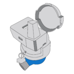

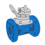

Fire lines stay quiet for years. Then one event demands sudden high flow. If the meter is wrong, the complaint becomes a safety risk.
Fire service water meter field lessons show one pattern clearly: failures often come from long static periods, sudden high-flow demand, and incorrect meter selection. I treat fire service metering as a high-risk application, not a normal billing point.
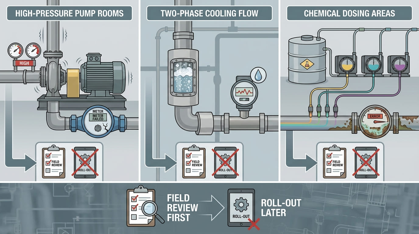
I usually slow the discussion down before model selection. A fire service meter may look like a large water meter, but the operating profile is very different. It may sit almost still, then face pump flow, reverse hydraulic effects, pressure shock, and emergency demand.
What Makes Fire Service Metering Different?
Normal meters follow daily consumption. Fire lines do not. This quiet period creates false confidence, so I check the duty cycle first.
Fire service metering is different because the line may stay static for long periods and then face sudden high flow during testing or fire events. The meter must suit both low or zero-flow monitoring and emergency hydraulic demand.
The Duty Cycle Is the First Risk
I do not start a fire service project by asking only for DN size. I first ask how the line works. Is it a dedicated fire line? Is it a combined domestic and fire service line? Is the meter used only for monitoring? Is it used for billing domestic bypass consumption? Does the line feed sprinklers, hydrants, fire pumps, tanks, or a mixed building system?
The most important point is the duty cycle. Many fire lines are static most of the time. Flow may be close to zero for months. Then the system may suddenly move to a high-flow test or emergency condition. This is very different from a residential or commercial meter with frequent daily flow.
That pattern creates a special complaint risk. If the meter is selected like a normal consumption meter, it may not handle the sudden flow requirement. If it is oversized only for fire flow, it may not record low domestic bypass flow well. If it is too restrictive, pressure loss may become a serious issue during fire service demand.
Combination meters are often considered in mixed-flow applications because they can use a small meter path for lower flow and a main path for higher flow. ISO 4064 includes specific references to combination meters and notes that combination meters with two indicating devices must apply register requirements to both indicating devices [2]. This supports the idea that both low-flow and high-flow indication paths must be treated carefully.
I also pay attention to protection devices. A water meter should include sealable protection devices to prevent dismantling or modification of the meter, adjustment device, or correction device before and after correct installation [2]. In fire service applications, unauthorized modification is not only a billing issue. It can become a safety and compliance issue.
| Fire Service Feature | Why It Is Different | What I Check |
|---|---|---|
| Long static condition | Deposits, dry chambers, and hidden faults may not appear early | Absence of flow behavior and inspection plan |
| Sudden high flow | Emergency demand can exceed normal consumption profile | Q3, Q4, pressure loss, and overload behavior |
| Mixed domestic and fire flow | Low-flow and high-flow needs conflict | Combination meter or bypass design |
| High consequence of failure | Failure may affect safety systems | Certification, test reports, and maintenance schedule |
| Tamper sensitivity | Unauthorized changes create risk | Sealing and protection devices |
A fire service meter supports measurement, monitoring, and control documentation. It does not replace fire system hydraulic design, pump testing, valve inspection, sprinkler engineering, or local code compliance.
Flow and Pressure Requirements in Fire Systems?
A fire line cannot be sized only by pipe diameter. The wrong flow boundary can create false readings, pressure loss, or failure.
Fire service meter selection should define minimum monitoring flow, normal standby condition, test flow, emergency flow, overload flow, pressure range, and pressure loss. ISO 4064 includes tests for static pressure, water pressure, reverse flow, pressure loss, and indication error [5].
I Separate Standby, Test, and Emergency Flow
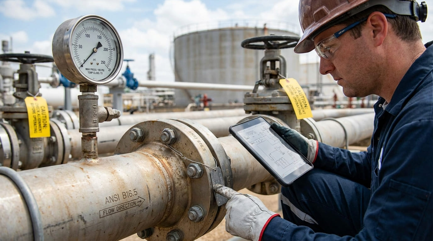
I usually ask for three flow conditions. The first is standby or near-zero condition. The second is routine test flow. The third is fire event or maximum design flow. These conditions should not be mixed into one vague statement such as “large flow meter required.”
The meter must be able to operate within its declared measuring range under defined conditions. ISO 4064 performance testing includes error of indication, static pressure, water pressure, reverse flow, and pressure loss tests [5]. These items are relevant because fire service lines may face high pressure, backflow influence, flow testing, and hydraulic disturbance.
Durability is also important. ISO 4064 describes durability testing to verify a water meter when subjected to continuous, permanent, and overload flow conditions [1]. The test can subject the meter to a constant flow rate of Q3 or Q4 for a specified duration [1]. This matters because a fire service meter may not flow every day, but when it does flow, the event can be severe.
For field review, I also check whether the system can create cavitation, air pockets, or parasitic wear. ISO 4064 test installation guidance states that devices in the piping system shall not cause cavitation phenomena or other types of parasitic wear of the meter [3]. It also states that meters and connecting pipes should be suitably bled of air [3]. In real fire lines, trapped air and pump starts can create unstable behavior that later appears as an abnormal complaint.
| Flow or Pressure Item | Why I Ask | Risk If Missing |
|---|---|---|
| Minimum detectable flow | Checks monitoring or bypass flow need | Under-registration complaint |
| Normal standby condition | Confirms long static behavior | Hidden fault or stagnant water issue |
| Routine test flow | Matches fire system test practice | Wrong meter overload assumption |
| Emergency design flow | Protects fire response capacity | Pressure loss or meter damage risk |
| Q3 and Q4 | Defines permanent and overload flow boundary | Incorrect meter selection |
| Pressure loss | Protects downstream fire system demand | Reduced available pressure |
| Inlet and outlet pressure | Shows hydraulic stress | Leakage or abnormal wear |
I do not recommend selecting by pipe size alone. The selected meter should match the actual working flow profile and the required emergency flow. If the meter is too large, low-flow monitoring may be weak. If the meter is too small, pressure loss and overload risk may increase.
Typical Complaint and Failure Modes?
Fire meter complaints often arrive late. The meter looked fine because nothing happened. Then a test exposes the weak point.
Typical fire service meter complaints include no registration after long standby, low reading at test flow, excessive pressure loss, leakage, register damage, reverse flow effects, air-related errors, and smart alarm or data transmission faults.
Why the Complaint Often Looks Abnormal
I see one repeated pattern. The meter may work normally during factory inspection and installation. Then it stays almost still. No one notices a hidden issue. Months later, a pump test or fire drill creates sudden high flow. The meter gives an unexpected reading, leaks, vibrates, or triggers a complaint.
This does not always mean the meter is defective. It may mean the wrong model was selected, the line was not flushed, the meter was installed near a pump or valve, air was trapped, or the meter was exposed to pressure shock. It may also mean the meter was not suitable for the required high-flow duty.
ISO 4064 performance tests include absence of flow for electronic water meters or meters with electronic devices [5]. This is relevant because long no-flow periods are common in fire service lines. If a smart meter is used, I also check how the device behaves during faults. ISO 4064 states that when a meter transmits data to peripheral equipment, the transmission shall be accompanied by a message indicating the presence of a fault [6]. This helps separate valid readings from fault conditions.
| Complaint | Possible Cause | My First Check |
|---|---|---|
| No reading during test | stuck mechanism, air, wrong model, blocked line | flow condition and meter status |
| Low reading | oversized meter, bypass issue, partial obstruction | Q3, R, installation, line flushing |
| Leakage | pressure shock, gasket issue, body stress | pressure record and installation support |
| High pressure loss | undersized meter or wrong type | pressure loss data and emergency flow |
| Reverse flow record | backflow or hydraulic transient | valve layout and reverse flow test basis |
| Fault alarm | electronic issue or system fault | alarm log and communication path |
| No remote data | weak signal or platform issue | gateway, SIM, coverage, reporting cycle |
For electronic or smart meters, alarms must be handled carefully. ISO 4064 allows automatic correction, stopping only the faulty device if the meter still complies, or a visible or audible alarm under defined fault handling rules [6]. If data is transmitted, the fault message should travel with the transmission [6]. I do not treat every alarm as a measurement failure. I first identify whether it is a sensor, power, memory, communication, or platform issue.
A fire service meter complaint should never be closed with a simple “replace meter” answer. I review complaint data, installation records, pressure data, test conditions, batch records, and any alarm logs. The high-risk nature of the application requires root-cause analysis.
Installation Pitfalls in Fire Lines?
A good meter can fail in a bad fire line. Pumps, bends, valves, and trapped air can turn testing into complaints.
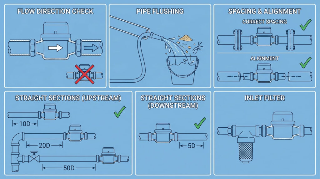
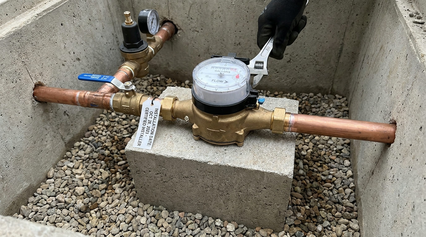
Fire line installation pitfalls include insufficient straight pipe, nearby pumps, fast-closing valves, trapped air, poor pipe support, wrong flow direction, inaccessible chambers, and missing pressure measurement points.
The Pipe Layout Can Decide the Result
I always ask for the installation drawing before confirming a fire service meter. A fire line often has pumps, check valves, isolation valves, bypasses, hydrant branches, and sharp bends. These parts can disturb flow or create pressure transients.
ISO 4064 test setup guidance includes water supply, pipework, flow-regulating devices, isolating valves, water temperature measurement, and means for checking flow rate and duration [1]. It also describes test pipework with flow-regulating devices, isolating valves, pressure measurement at inlet and outlet, and flow-interrupting devices [3]. These details remind me that flow testing is not only about the meter. It is about the entire hydraulic arrangement.
Air is another common pitfall. ISO 4064 states that meters and connecting pipes should be suitably bled of air [3]. In fire systems, air can remain in high points, dead legs, or after maintenance. When a pump starts, that air can pass through the meter and create unstable readings, noise, or mechanical stress.
Cavitation and parasitic wear are also concerns. ISO 4064 says the various devices in the test piping system shall not cause cavitation phenomena or other types of parasitic wear of the meter [3]. In a fire line, pump suction issues, throttled valves, and poor layout can create harsh hydraulic conditions.
| Installation Pitfall | Field Effect | Control Method |
|---|---|---|
| Meter too close to pump | unstable flow and vibration | follow straight pipe guidance |
| No pressure gauges | cannot diagnose pressure loss | add inlet and outlet pressure points |
| Trapped air | noise, unstable reading, damage risk | bleed air and check high points |
| Fast valve closure | pressure shock | review valve operation and surge control |
| Wrong direction | no reading or reverse reading | check flow arrow before commissioning |
| Poor pipe support | body stress and leakage | support pipework, not meter body |
| Inaccessible chamber | delayed inspection | design for maintenance access |
I also check whether the meter can be removed safely. Fire systems are critical. Maintenance access must allow isolation, inspection, replacement, and recommissioning without creating unsafe downtime. A meter buried in a tight chamber may pass installation acceptance but fail lifecycle maintenance.
Testing, Certification and Compliance Requirements?
Fire service meters need more than a datasheet. If the test boundary is unclear, compliance becomes a debate after failure.
Testing and compliance should cover metrological performance, pressure, reverse flow, pressure loss, durability, temperature, register protection, fault handling, and local fire approval requirements. ISO 4064 includes these water meter performance test categories [5].
I Check Both Meter Standard and Fire Approval Path
I treat ISO 4064 as an important water meter standard, but not as a complete fire protection approval. It helps define metrological and performance testing. Fire systems may also require local fire codes, consultant approval, civil defense approval, UL/FM listed components, backflow requirements, or other national rules depending on the market.
ISO 4064 performance test programs include static pressure, error of indication, absence of flow, water temperature, overload water temperature where applicable, water pressure, reverse flow, and pressure loss [5]. These items are useful for reviewing a fire service meter because the application may face high pressure, reverse hydraulic effects, and pressure-loss sensitivity.
Durability testing is also relevant. The standard describes verification of meter durability under continuous, permanent, and overload flow conditions, including tests at Q3 or Q4 for specified duration [1]. In fire service applications, I pay special attention to Q4 because sudden overload flow can occur during system testing or emergency operation.
For temperature, ISO 4064 describes tests to measure the effects of water temperature on meter indication errors, including testing at Q2 with defined inlet temperature conditions and at the maximum admissible temperature of the meter [4]. Fire service water is usually cold, but mechanical rooms, outdoor chambers, and warm climates can still affect meter materials and electronics.
| Compliance Item | What I Request |
|---|---|
| Water meter standard | ISO 4064, OIML R49, or project-required standard |
| Fire approval | local fire authority, consultant, or civil defense requirement |
| Flow ratings | Q3, Q4, pressure loss, overload data |
| Pressure tests | static pressure and working pressure evidence |
| Reverse flow | test basis and field backflow control |
| Register protection | sealed protection against modification |
| Smart fault handling | alarm and transmitted fault message behavior |
| Installation manual | straight pipe, orientation, pressure, and maintenance rules |
I also check sealing and tamper protection. ISO 4064 requires protection devices that can be sealed to prevent dismantling or modification of the meter or its adjustment device without evidence [2]. This is important in fire service lines because unauthorized bypass or adjustment can affect both billing and safety documentation.
Real-World Cases from High-Risk Facilities?
High-risk facilities expose weak specifications quickly. Hospitals, malls, factories, and warehouses cannot accept vague meter selection.
In high-risk facilities, fire service meter problems often come from mixed domestic and fire flow, pump-room pressure shock, poor flushing, inaccessible installation, and smart communication gaps.
Field Patterns I Often See
I will describe common project patterns rather than confidential customer cases. The first pattern appears in large commercial buildings. The same line may support domestic consumption monitoring and fire demand. A normal large meter may handle high flow but miss low bypass consumption. A small meter may read low flow but restrict fire demand. In this case, I study whether a combination meter or a separate metering arrangement is suitable.
The second pattern appears in pump rooms. The meter is installed too close to pumps, elbows, or fast-closing valves. During a fire pump test, the reading becomes unstable, or the meter shows vibration. ISO 4064 test arrangements include pressure measurement at the inlet and outlet and require devices not to cause cavitation or parasitic wear [3]. This reflects a practical field need: pressure and hydraulic behavior must be measurable.
The third pattern appears in warehouses and industrial parks. The fire system sits idle. After months, a test creates sudden flow. Debris, trapped air, or a partly closed valve creates a complaint. Because the system is high-risk, the facility team may demand immediate replacement. I still ask for a root-cause review before deciding.
The fourth pattern appears in smart metering projects. The meter measures flow, but the remote reading is missing. The problem may be underground installation, metal covers, weak NB-IoT coverage, poor LoRa gateway placement, wrong meter registration, or platform settings. A smart meter can support remote data collection and alarm management, but it cannot replace network design, gateway power, SIM management, or field response.
| Facility Type | Common Fire Meter Risk | What I Verify |
|---|---|---|
| Hospital | high consequence of downtime | bypass, isolation, and maintenance plan |
| Shopping mall | mixed use and large peak demand | combination meter need and pressure loss |
| Factory | pump vibration and dirty water | hydraulic layout and flushing record |
| Warehouse | long idle periods | test schedule and absence-of-flow behavior |
| Industrial park | communication and pressure zones | gateway plan and pressure logging |
I prefer pilot verification for unusual facilities. A pilot should include flow test, pressure observation, remote reading test if smart, and maintenance access review. Actual results depend on local field conditions.
Selecting and Maintaining Fire Service Meters Safely?
A fire service meter decision should be conservative. The meter must support safety, measurement, and maintainability under real site conditions.
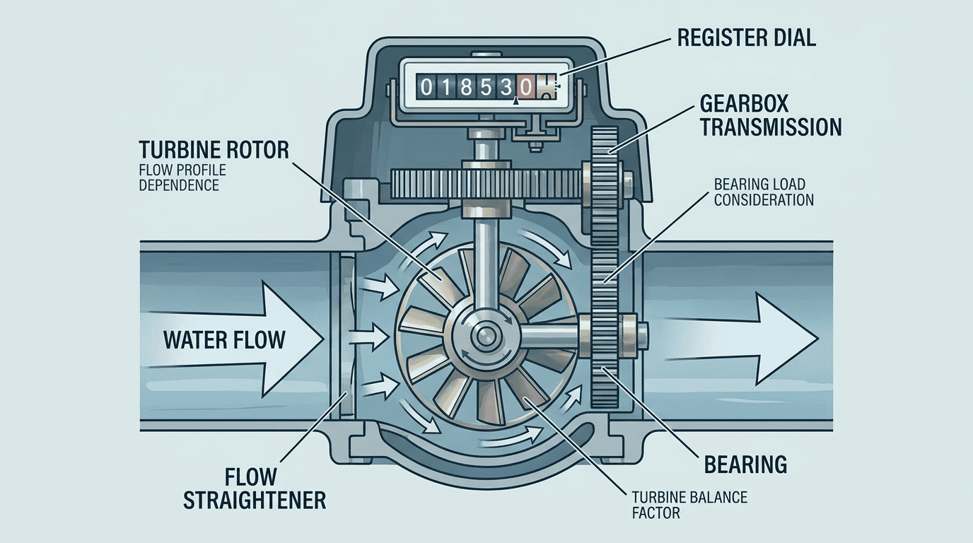
Select and maintain fire service meters by defining the flow profile, Q3, Q4, pressure loss, pressure rating, installation layout, compliance route, inspection schedule, and failure response plan before procurement.
My Practical Checklist for Safer Projects
I use a checklist before approving a fire service meter. It starts with application. I ask whether the meter is for a dedicated fire line, combined domestic and fire service, sprinkler supply, hydrant branch, fire pump outlet, or facility monitoring. Then I define the hydraulic boundary.
The tender should state meter size, Q3, Q4, pressure loss limit, normal pressure, maximum pressure, pressure shock risk, installation orientation, straight pipe requirement, temperature class, protection level, and certification requirement. ISO 4064 includes tests for pressure loss, water pressure, reverse flow, static pressure, and indication error [5]. These are useful tender references when the buyer wants comparable technical documents.
I also ask for durability evidence. ISO 4064 durability testing can subject meters to Q3 or Q4 for specified duration to verify behavior under permanent and overload flow conditions [1]. For a fire service meter, I want to know how the meter behaves when high flow occurs after long quiet periods.
Maintenance is not optional. Fire lines need regular inspection, test flow verification, pressure checks, air bleeding where required, valve position checks, and record keeping. If the meter is smart, the maintenance plan should include battery status, signal quality, alarm review, platform data, and fault messages. ISO 4064 requires transmitted data to include a message indicating the presence of a fault when the meter transmits data to peripheral equipment [6].
| Procurement and Maintenance Item | What I Specify |
|---|---|
| Application boundary | dedicated fire, combined service, sprinkler, hydrant, pump line |
| Flow profile | standby, low flow, test flow, emergency flow |
| Meter parameters | DN, Q3, Q4, pressure loss, pressure rating |
| Installation | straight pipe, orientation, support, air bleeding, access |
| Compliance | ISO/OIML documents and local fire approvals |
| Protection | sealed devices and tamper evidence |
| Smart system | communication method, gateway, SIM, platform, alarm rules |
| Maintenance | inspection cycle, flow test, pressure record, complaint process |
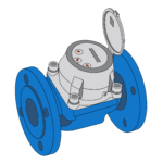
YOUNIO can support mechanical water meters, Woltman meters, turbine meters, large-diameter meters, ultrasonic meters, and smart AMR/AMI options for different applications. But I would still verify the final selection against the fire system design, local approval route, and field pilot where the risk is high.
The safest selection is not always the largest meter. It is the meter that matches the actual flow profile, pressure condition, installation layout, and compliance requirement. In fire service applications, I treat long static condition plus sudden high flow plus wrong model selection as the main complaint triangle.
Conclusion
Specify fire service meters by flow profile, Q3, Q4, pressure loss, installation, compliance, and maintenance access. Wrong assumptions create high-risk complaints.
Need help applying this to your project?
Send your meter size, target market, and certification requirement. YOUNIO will reply with a technical checklist.