


Piccoli dettagli di progettazione all'interno di un contatore dell'acqua meccanico possono decidere se un progetto procede senza intoppi o si trasforma in un file di reclamo. Ho visto molti casi in cui quella che sembrava una piccola deviazione della sigillatura è diventata un problema ripetuto per l'intero lotto.
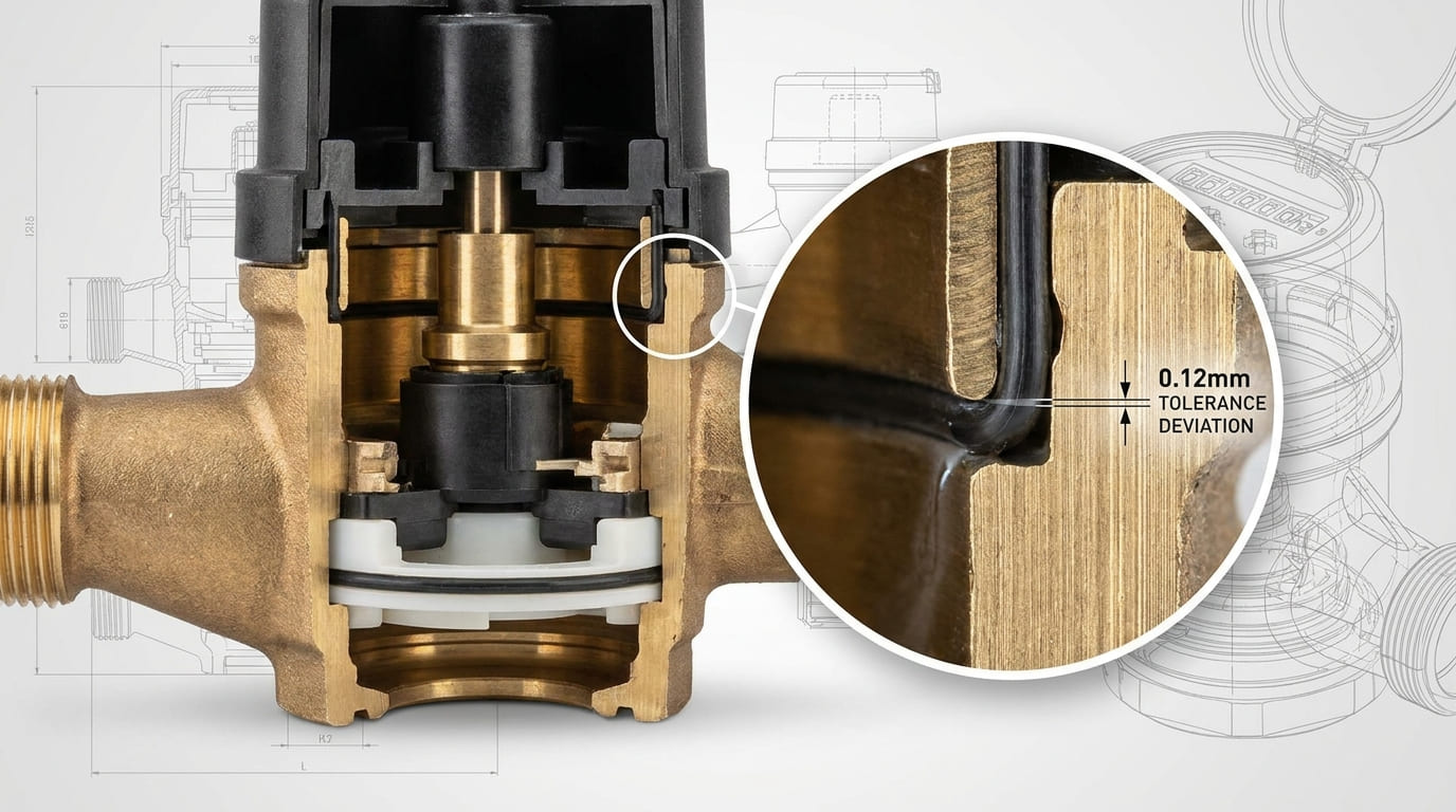
La lezione fondamentale è semplice: un errore di tolleranza di sigillatura di 0,1–0,2 mm può sembrare minimo su un metro, ma su decine di migliaia di unità può trasformarsi in un problema di microperdite a livello di sistema. Una buona progettazione del contatore dell'acqua meccanico dipende dalla disposizione dei componenti, struttura di tenuta, scelta del materiale, resistenza alla corrosione, e uno stretto controllo del processo, non solo su una caratteristica.
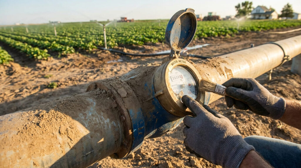
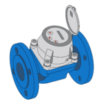
Quando guardo un contatore dell'acqua meccanico, Non vedo solo un corpo in ottone o plastica con un registro sopra. Vedo un sistema idraulico sigillato, un meccanismo di misurazione, una via di trasmissione, una struttura espositiva, e diverse interfacce in cui piccoli errori di progettazione possono diventare fallimenti sul campo. Un metro deve mantenere l'acqua nel giusto percorso, proteggere il suo sistema di indicazione, resistere alla corrosione, e sopravvivere ad anni di pressione, cambiamento di flusso, e variazione della qualità dell’acqua. Ecco perché le “perdite nella progettazione dei contatori dell’acqua meccanici” non sono solo un argomento di produzione. È un argomento di affidabilità.
Componenti principali all'interno di un contatore dell'acqua meccanico?
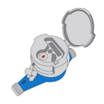
Un contatore dell'acqua meccanico solitamente include un corpo, camera di misurazione, elemento di misura mobile, sistema di trasmissione, registro, finestra trasparente, e punti di tenuta. Ognuna di queste parti influisce perdita rischio, rischio di attaccamento, e prestazioni a vita.
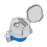
Il dispositivo indicatore deve fornire un'indicazione visiva affidabile e facilmente leggibile, e il display è tipicamente protetto da una finestra trasparente. Il contatore necessita inoltre di dispositivi di protezione sigillabili per impedirne lo smantellamento o la modifica dopo l'installazione.
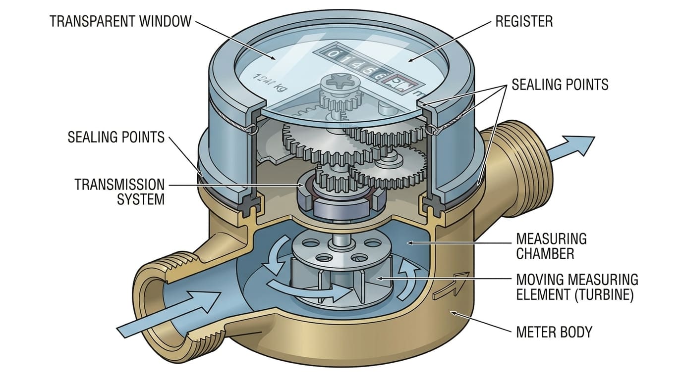
All'interno di un tipico contatore dell'acqua meccanico, il corpo costituisce il confine di pressione. Qui è dove entra l'acqua, attraversa la zona di misurazione, ed esce. Dentro quel corpo, la camera di misurazione controlla il modo in cui l'elemento mobile risponde al flusso. A seconda del tipo di contatore, questa parte mobile può essere una girante, turbina, o pistone. Quindi un sistema di trasmissione trasferisce il movimento dal lato umido al lato del registro secco. In alto, il registro e il dispositivo indicatore mostrano il volume misurato in modo chiaro e inequivocabile.
Presto molta attenzione alle interfacce. Quelli sono i luoghi in cui due parti si incontrano, ruotare, premere insieme, o isolare le zone umide e asciutte. L'articolazione del corpo, coperchio della camera, finestra di registrazione, alloggiamento del quadrante, e le superfici dei connettori dipendono tutte dalla corretta sigillatura. Se uno qualsiasi di questi punti ha uno scarso controllo dimensionale, il misuratore potrebbe non fallire in modo drammatico. Potrebbe invece creare una microperdita lenta e difficile da rilevare. Questo tipo di problema è spesso più pericoloso in lotti di grandi dimensioni perché si diffonde silenziosamente.
La norma ricorda inoltre che il contatore completo deve essere realizzato con materiali resistenti alla corrosione interna ed esterna, o protetti da idoneo trattamento superficiale. Questo mi dice che il layout dei componenti interni è solo metà della storia. L'intero gruppo deve rimanere stabile in condizioni reali di acqua e ambiente.
| Componente | Funzione principale | Principale rischio di guasto |
|---|---|---|
| Corpo del misuratore | Mantiene la pressione e il percorso del flusso | Crepa, corrosione, perdita |
| Camera di misurazione | I controlli scorrono attraverso il meccanismo | Indossare, attaccarsi |
| Elemento in movimento | Converte il flusso in movimento | Attrito, marmellata, sottoregistrazione |
| Sistema di trasmissione | Trasferisce il movimento alla registrazione | Scivolamento, Indossare |
| Registrati e chiama | Visualizza chiaramente il volume misurato | Appannamento, rischio mal interpretato |
| Finestra trasparente | Protegge il dispositivo di indicazione | Condensazione, debolezza della sigillatura |
| Interfacce di sigillatura | Prevenire la fuoriuscita e l'ingresso di acqua | Microperdite, infiltrazioni a lungo termine |
In che modo la progettazione delle tenute influenza le prestazioni nel corso della vita?
La progettazione della tenuta è una delle parti più importanti dell'affidabilità del contatore dell'acqua meccanico. Un contatore può superare una breve ispezione e sviluppare comunque infiltrazioni a lungo termine se la struttura di tenuta è troppo sensibile alla deriva della tolleranza, invecchiamento dei materiali, o cicli di pressione.
Una buona progettazione della tenuta deve controllare le perdite sotto pressione, resistere all'invecchiamento, e rimanere stabili durante l'installazione e le condizioni di test. Anche il contatore ed i tubi di collegamento devono essere opportunamente spurgati dall'aria, e l'installazione dovrebbe evitare la cavitazione e l'usura parassitaria che possono peggiorare lo stress dei componenti .
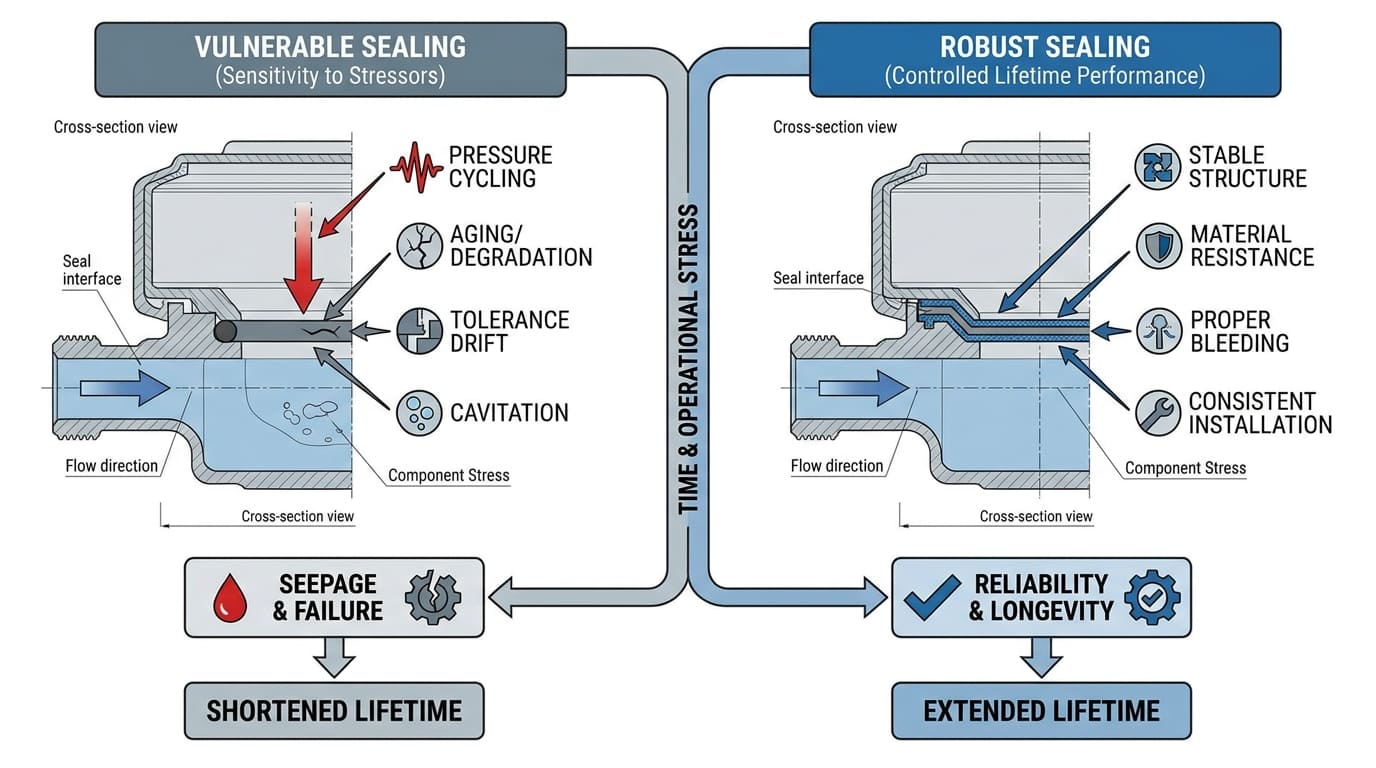
Dico spesso ai team di progetto che i problemi di perdite raramente sono solo “problemi di tenuta”. Sono problemi del sistema di progettazione. Una guarnizione funziona solo quando le dimensioni della scanalatura, tasso di compressione, durezza del materiale, finitura superficiale, e la forma del corpo lavorano tutti insieme. Se un lato di quella pila cambia troppo, la guarnizione potrebbe ancora avere un bell'aspetto durante l'assemblaggio ma funzionare male nel tempo.
Lo standard non ci fornisce una regola diretta per ogni progetto di O-ring o guarnizione, ma ci fornisce un quadro più ampio. I materiali devono essere atossici, non contaminante, e biologicamente inerte ove rilevante, e il contatore pieno deve resistere alla corrosione. Queste non sono note a margine. Influiscono direttamente sulla durata delle guarnizioni. Se il corpo si corrode, se una sede di tenuta cambia forma, o se il trattamento della superficie è scadente, le prestazioni di tenuta possono diminuire anche se il materiale di tenuta stesso era accettabile il primo giorno.
Penso anche all'aria intrappolata, fluttuazione della pressione, e testare la configurazione. Iso 4064-2 richiede che il contatore ed i tubi di collegamento siano opportunamente sfiatati, e richiede che i dispositivi di installazione non causino cavitazione o altra usura parassitaria. In termini semplici, cattive condizioni idrauliche possono creare ulteriore stress sulle parti interne. Tale stress può accelerare l'usura delle superfici di tenuta e delle parti mobili. Quindi la progettazione delle tenute non riguarda solo le dimensioni statiche. Riguarda anche il modo in cui il contatore vive in condizioni di flusso reali.
Il ruolo delle tolleranze e dei materiali?
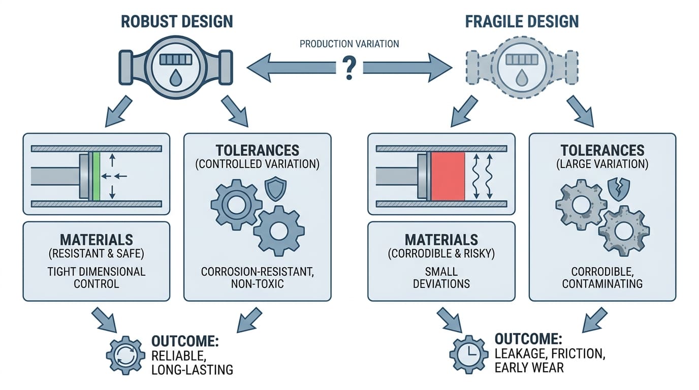
Tolleranze e materiali determinano se un design è robusto o fragile. Una buona progettazione del contatore dovrebbe funzionare anche quando la variazione della produzione rimane sotto controllo. Un design debole funziona solo quando tutto è perfetto.
I materiali devono essere resistenti alla corrosione o adeguatamente protetti, e il contatore dovrebbe essere realizzato con materiali non tossici e non contaminanti nei punti in cui l'acqua lo attraversa. Il rigoroso controllo dimensionale è importante poiché piccole deviazioni nelle interfacce di tenuta e di movimento possono creare perdite, attrito, e usura precoce.
In produzione, Considero la tolleranza come un effetto moltiplicativo. UN 0.1 Lo spostamento di mm potrebbe non sembrare serio in una sala riunioni. Ma in un metro, 0.1–0,2 mm possono modificare la compressione della guarnizione, gioco dell'albero, contatto della camera, o registrarsi abbastanza in forma da creare rischi sul campo. Se produci dieci campioni, il problema potrebbe nascondersi. Se ne produci cinquantamila, il problema diventa un modello di reclamo.
La scelta dei materiali conta altrettanto. Se una parte è a contatto con l'acqua, dovrebbe resistere alla corrosione e rimanere dimensionalmente stabile attraverso la pressione e il tempo. Se una finestra trasparente fa parte del dispositivo indicatore, la progettazione dovrebbe inoltre prevenire o eliminare la formazione di condensa laddove vi sia rischio. Ciò è importante perché alcuni apparenti reclami di “ingresso di acqua interna” iniziano come errori di gestione della condensa piuttosto che come perdite del corpo.
Per parti in movimento, tolleranza e materiale lavorano insieme. Se la distanza è troppo stretta, particelle, accumulo di durezza, o lo spostamento termico può aumentare l'attrito. Se la distanza è troppo ampia, l'efficienza e la precisione possono risentirne. Un design robusto utilizza coppie di materiali e tolleranze che rimangono stabili anche quando la qualità dell'acqua non è ottimale. È qui che la progettazione matura differisce dalla progettazione puramente teorica.
| Fattore di progettazione | Se troppo stretto | Se troppo lento |
|---|---|---|
| Compressione della guarnizione | Deformazione, invecchiamento precoce | Microperdite, infiltrazioni |
| Sgombero della Camera | Attaccare, aumento dell'attrito | Perdita di controllo, Indossare |
| Adattamento albero/cuscinetto | Inceppa e trascina | Vibrazione, instabilità |
| Registra l'adattamento della finestra | Rischio di stress o appannamento | Ingresso di umidità |
Alla ricerca di un fornitore affidabile di contatori dell'acqua?
YOUNIO produce macchinari e ultrasonico contatori d'acqua da DN15 a DN500, Certificato MID e testato ISO 4064. Campioni gratuiti e rapporti sui test di fabbrica disponibili per acquirenti qualificati.
Caso di studio: 0.1–Deviazione di 0,2 mm e microperdite del lotto?
Una deviazione di 0,1–0,2 mm in una dimensione correlata alla sigillatura può causare microperdite ripetute nell'intero lotto. Un metro può mostrare solo leggere infiltrazioni. Ma su scala di progetto, la questione diventa sistematica.
Questo tipo di problema diventa serio perché il contatore deve rimanere durevole e stabile in condizioni di servizio reali, e anche i piccoli difetti possono moltiplicarsi in reclami di ampio respiro quando la stessa deriva dimensionale appare su molte unità .
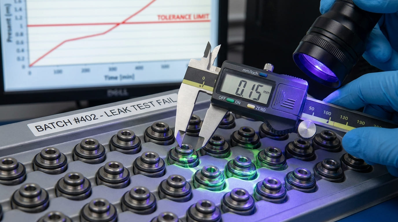
Ho riscontrato questo tipo di problema nel lavoro di revisione in fabbrica e sul campo. Una scanalatura di tenuta o l'altezza della sede del coperchio si sposta di soli 0,1–0,2 mm. Durante il montaggio, la linea funziona ancora. Il test della pressione potrebbe non rifiutare ogni unità perché la perdita è troppo piccola o si sviluppa successivamente. All'inizio, il lotto appare normale. Quindi dopo l'installazione, i file dei reclami iniziano a mostrare uno schema: leggera umidità intorno alla giunzione, infiltrazioni a lungo termine nell'area del registro, o umidità inspiegabile in una percentuale di contatori installati.
Per questo chiamo pericolosi gli errori dimensionali di piccole dimensioni. Non sempre creano drammaticità, fallimento immediato. Creano debolezza ripetibile. In un lotto di decine di migliaia di unità, anche un basso tasso di reclami diventa un grave problema operativo.
Il quadro standard aiuta a spiegare perché questo è importante. Il contatore pieno deve resistere alla corrosione ed essere costruito correttamente. Le installazioni di prova devono evitare la cavitazione e l'usura parassitaria, e il contatore e i tubi dovrebbero essere spurgati dall'aria. Questi ci ricordano che l’affidabilità non si costruisce solo con il disegno nominale. È costruito tramite il controllo delle dimensioni, capacità di processo, e assemblaggio stabile. Un progetto troppo sensibile alla variazione di 0,1–0,2 mm è un progetto che necessita di miglioramenti, non scuse.
Tipiche modalità di guasto per incollaggio e usura?
I contatori meccanici di solito si guastano attaccandosi, aumento della resistenza, Indossare, o trasmissione instabile prima che falliscano per rottura completa del corpo. Questi fallimenti spesso si accumulano lentamente.
Tipiche modalità di incollaggio e usura includono l'inceppamento dovuto ai detriti, aumento dell'attrito dovuto a giochi errati, usura parassita dovuta a cattive condizioni idrauliche, e corrosione a lungo termine o degrado del materiale .
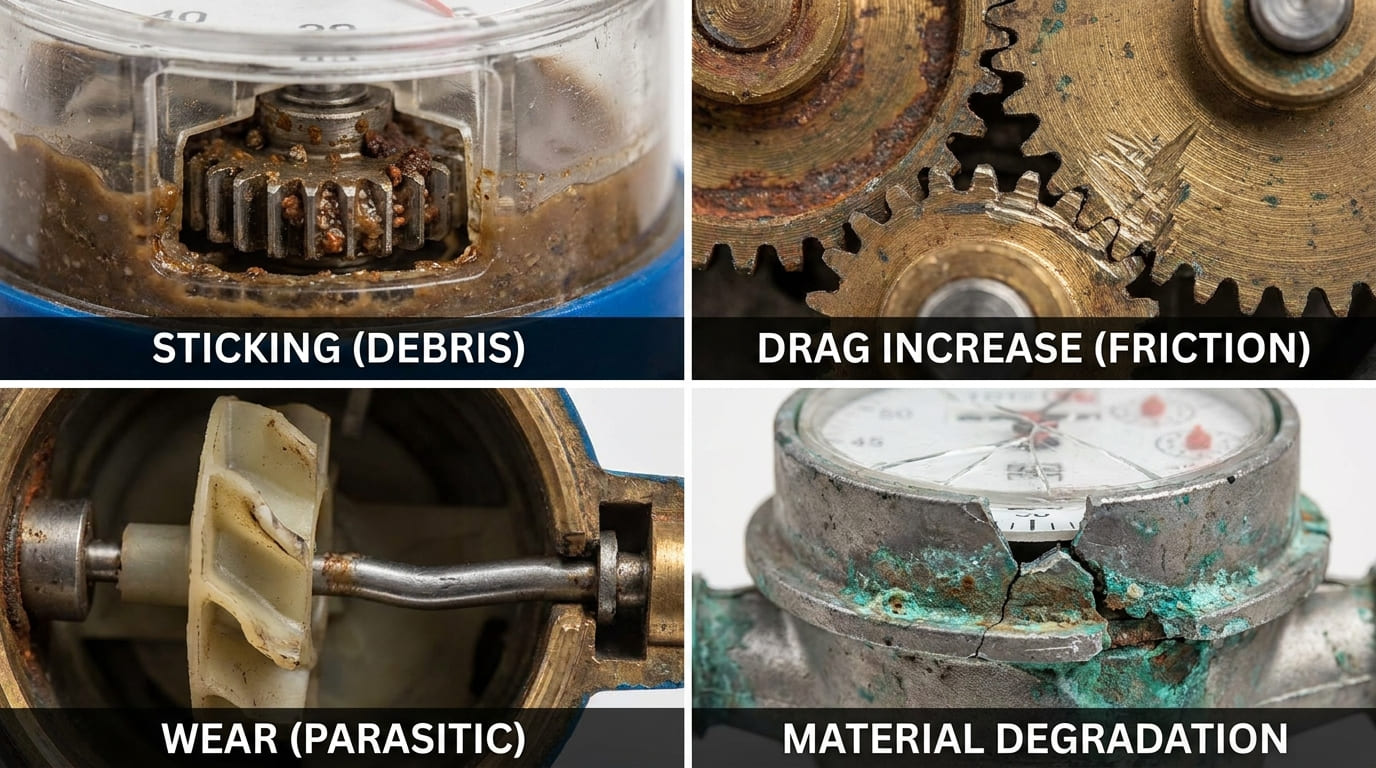
Quando indago su un reclamo persistente, Di solito lo separo in tre domande. Primo, l'elemento mobile aveva abbastanza gioco?? Secondo, la qualità dell'acqua ha portato particelle, scala, o depositi biologici nella camera? Terzo, l'ambiente di flusso e pressione ha creato ulteriore stress?
Iso 4064-2 è utile in questo caso perché avverte che i dispositivi di prova e di connessione non devono causare cavitazione o altra usura parassitaria del misuratore. Prendo questa idea anche pensando sul campo. Se un contatore si trova in cattive condizioni idrauliche, interruzione improvvisa, sacche d'aria, o forti disturbi locali possono accelerare l'usura interna. Anche se il design è decente, cattive condizioni operative possono spingerlo verso un attrito precoce e un incollaggio.
Osservo anche attentamente la corrosione. Iso 4064 richiede materiali resistenti alla corrosione o un trattamento superficiale adeguato . La corrosione non danneggia solo l'apparenza. Può cambiare le superfici, indebolire gli attacchi, e influenzano i percorsi di movimento. Nei contatori meccanici, piccoli aumenti della resistenza possono ridurre la risposta a basso flusso molto prima che il misuratore appaia “rotto”. Questo è il motivo per cui la mancata usura viene spesso vista inizialmente come una sottoregistrazione, partenza ritardata, o movimento intermittente.
| Modalità di fallimento | Causa tipica | Quello che vedo di solito |
|---|---|---|
| Girante inceppata | Detriti, spazio stretto | Basso flusso, nessuna registrazione |
| Trascinamento della camera | Scala, aumento dell'attrito | Risposta lenta, sotto-lettura |
| Usura della trasmissione | Usura meccanica a lungo termine | Registro instabile o ritardato |
| Corrosione superficiale | Materiale o trattamento scadente | Contatto approssimativo, perdita, lagna |
| Usura da stress idraulico | Cavitazione o usura parassitaria | Danno interno prematuro |
Progettare per diverse qualità dell'acqua?
Un contatore dell'acqua meccanico non dovrebbe essere progettato come se tutta l'acqua fosse pulita e stabile. La qualità dell’acqua modifica il modello di guasto, quindi il design dovrebbe corrispondere all'ambiente di destinazione.
Perché i contatori dell'acqua devono utilizzare materiali idonei e resistere alla corrosione, le scelte progettuali dovrebbero riflettere se l'applicazione è esposta ad acqua dura, limo, chimica aggressiva, o condizioni variabili di temperatura e pressione.
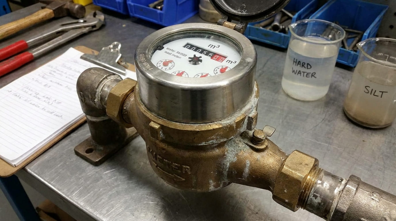
Nelle zone con acqua dura, Mi preoccupo di più dell'accumulo di calcare e del trascinamento delle parti in movimento. In acque sabbiose o limose, Mi preoccupo di più dell'abrasione e dell'adesione. In ambienti acquatici aggressivi, Presto più attenzione al materiale del corpo, trattamento interno, e compatibilità delle guarnizioni. Se la qualità dell'acqua è instabile, quindi il design “migliore” non è semplicemente quello con il minor attrito in un laboratorio pulito. È quello che rimane funzionante dopo anni in quella realtà locale.
Gli standard ci indicano ancora una volta la giusta direzione. I materiali a contatto con l'acqua devono essere non tossici e non contaminanti, e il misuratore dovrebbe resistere alla corrosione interna ed esterna. Iso 4064-2 rileva inoltre che la temperatura dell'acqua può influenzare le prestazioni in alcune situazioni di test. Anche se quell'estratto è più focalizzato sui test, mi ricorda che l'acqua non è un mezzo neutro. La temperatura e l'ambiente possono modificare il comportamento dei componenti.
Quindi, quando progetto o seleziono un contatore per mercati diversi, Non chiedo solo la portata. Chiedo che aspetto ha l'acqua, quali solidi trasporta, quanto spesso la pressione fluttua, e se le condizioni di installazione locali sono controllate. Queste risposte modellano il design della camera, selezione del materiale, e strategia di sigillatura.
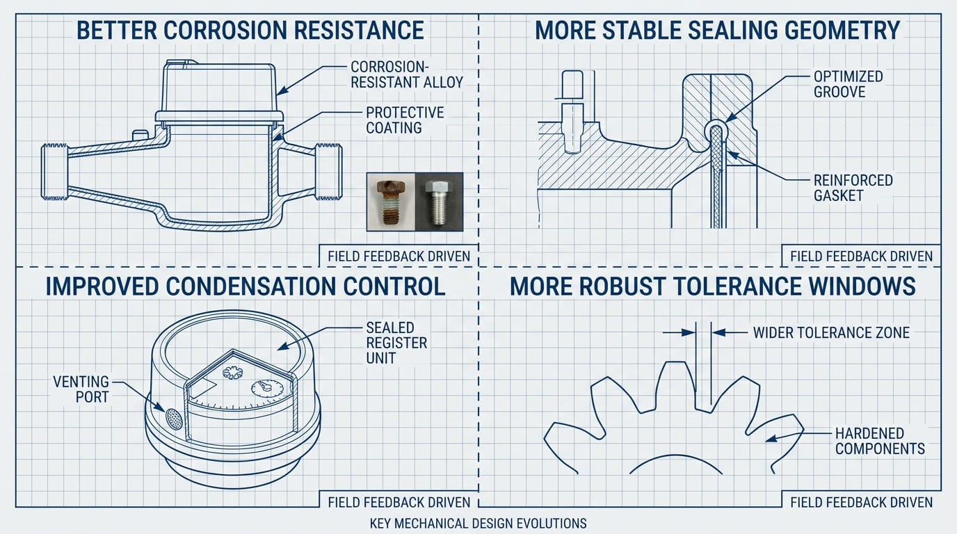
Cosa abbiamo cambiato nei nostri progetti nel corso degli anni?
Col tempo, una buona progettazione del contatore diventa meno una questione teorica e più una questione di rimozione di modelli di reclamo ripetuti. I cambiamenti migliori di solito provengono dal feedback sul campo, non solo dai disegni.
Le modifiche progettuali più utili a lungo termine spesso si concentrano su una migliore resistenza alla corrosione, geometria di tenuta più stabile, migliore controllo della condensa, e finestre di tolleranza più robuste.
Quando ripenso ai miglioramenti del design nel corso degli anni, Non penso prima agli aggiornamenti di marketing. Penso alla riduzione dei reclami. Impariamo di più dalle fughe di notizie lente, partenze appiccicose, vetri appannati, registrare l'umidità, e modelli di usura che si ripetono in determinate condizioni dell'acqua o stile di installazione.
La norma dice che dove c'è rischio di condensa sotto la finestra, il contatore dell'acqua deve incorporare dispositivi per la prevenzione o l'eliminazione della condensa. Potrebbe sembrare un piccolo dettaglio, ma è importante perché molti utenti giudicano innanzitutto la qualità in base a ciò che possono vedere. Un registro appannato o bagnato può suscitare sfiducia anche se la metrologia è ancora accettabile. Quindi un migliore controllo della condensa rappresenta un reale miglioramento dell'affidabilità.
Miglioriamo anche i progetti ampliando la robustezza della tolleranza. Se una caratteristica di sigillatura funziona solo all'interno di una fascia dimensionale molto stretta, allora il design è troppo fragile per la produzione su larga scala. Modifichiamo la struttura in modo che tolleri meglio la normale variazione del processo. Inoltre, esaminiamo i materiali con maggiore attenzione per verificare la corrosione e il contatto con l'acqua a lungo termine. Col tempo, questo tipo di lavoro riduce la possibilità che una piccola deviazione di 0,1–0,2 mm si trasformi in un problema di perdite a livello di batch.
Conclusione
All'interno di un contatore dell'acqua meccanico, piccole scelte progettuali determinano l'affidabilità a lungo termine. Geometria di tenuta, controllo della tolleranza, materiali resistenti alla corrosione, protezione dalla condensa, e il design orientato alla qualità dell'acqua aiutano a prevenire le perdite, attaccarsi, e i primi fallimenti。
Alla ricerca di un fornitore affidabile di contatori dell'acqua?
YOUNIO produce contatori d'acqua meccanici e ad ultrasuoni da DN15 a DN500, Certificato MID e testato ISO 4064. Campioni gratuiti e rapporti sui test di fabbrica disponibili per acquirenti qualificati.