


I used to blame the meter when readings looked wrong. I learned the real issue was often the site and not the meter itself under ISO 4064 rules regarding installation and conditions.
If I must choose between multi‑jet and single‑jet, I start with flow profile, water quality, pipe layout, とISO 4064 installation requirements. The right type needs the right conditions to stay within MPE (Maximum Permissible Error) limits.
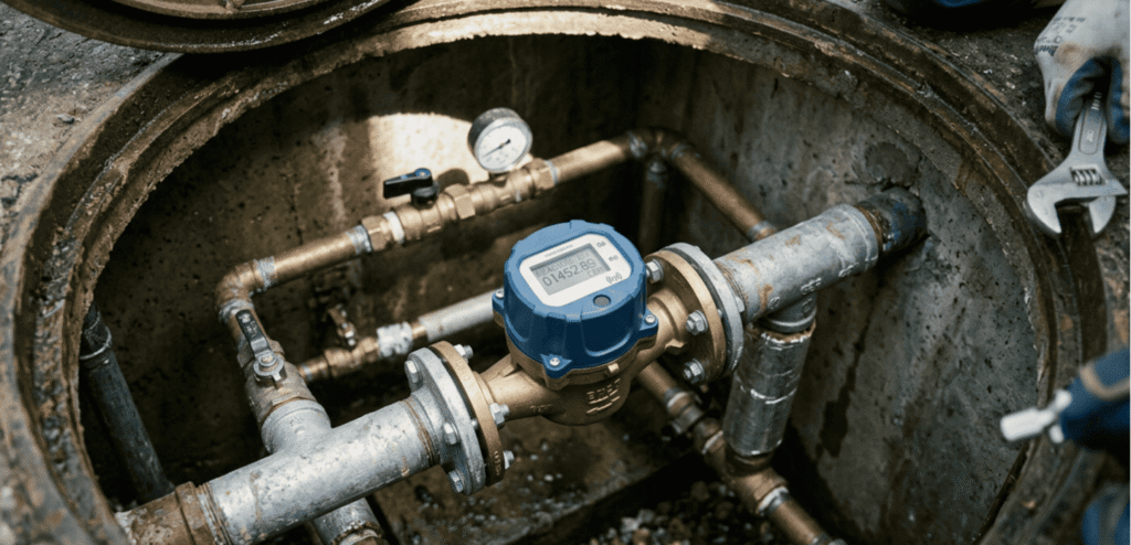
I have installed both types in homes, hotels and factories. I have opened chambers, bled air and checked pressure. I have seen sand and scale inside strainers after nearby pipe work. I have learned that most “inaccurate” complaints come from ignored ISO 4064 installation needs and not a failed meter.
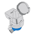
How Single‑Jet Water Meters Work?
Many people think a single‑jet meter is simple and cheap. That is true. It is also sensitive to site conditions if the pipe is not stable and clean.
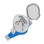
あ single‑jet meter uses one tangential jet that drives an impeller. It reads well at common domestic flows. It can be small, light, and low cost. It can suffer when debris, air or turbulence enters the chamber. Good installation and clean water help it perform well for years.
How the single‑jet principle behaves
A single‑jet design places one jet on the impeller. Water pushes the impeller at a speed linked to flow. The register counts turns. The design is simple. The price is often lower. The sensitivity can be high at mid flow. The weakness shows when air, sand or scale enter. I have seen upstream work fill strainers and chambers with solids, and that changes readings until we clean the meter. Strainers help, but good upstream flushing after maintenance helps more. If the upstream pipe has bends, valves or a nearby pump, the flow can be distorted. The meter then needs straight pipe lengths to stabilize flow and meet the MPE limits on site, as the standard requires. During testing, labs bleed air, control pressure and hold other influences within operating limits, and we should mirror these conditions in field installs to protect accuracy.
| Aspect | Single‑Jet Strength | Single‑Jet Weakness | Field Tip |
|---|---|---|---|
| Cost | Lower | — | Use for large rollouts |
| Flow sensitivity | Good at mid flow | Weaker at very low flow | Verify Q1 demand |
| Debris tolerance | Moderate | Sensitive to sand/scale | Flush after pipe work |
| Install needs | Straight lengths | Air bleeding | Bleed and level the meter |
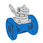
How Multi‑Jet Water Meters Work?
People choose multi‑jet when they want stable readings across a wider range. The design spreads flow and reduces point loads on the impeller.
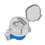
あ multi‑jet meter uses several small jets that strike the impeller evenly. The flow distribution improves stability and can lower the impact of turbulence. It often keeps good accuracy at low flows. It can show higher pressure loss at peak flows due to geometry and screens.
How multi‑jet stabilizes the flow
A multi‑jet design puts many jets around the impeller. Each jet contributes small momentum. The impeller rotates in a balanced way. This balance improves reading stability when the upstream layout is not ideal. I have used multi‑jet meters in buildings with elbows and tees near the chamber. The straight lengths still matter, とISO 4064 asks for enough straight pipe or a flow straightener,so the installed meter meets MPE on site. When we ignore this, the field accuracy slips, even with a multi‑jet. During tests, we measure errors at defined ranges like Q1, Q2 and Q3 (OIML flow rates) while we keep pressure above 0.03 MPa, and we hold other influences within rated conditions. I ask my teams to copy these simple controls in field checks. We bleed air, we confirm outlet pressure, and we confirm temperature is within rating. These small steps mirror the lab and protect the reading.
| Aspect | Multi‑Jet Strength | Multi‑Jet Weakness | Field Tip |
|---|---|---|---|
| Low flow accuracy | Often better | — | Validate Q1 patterns |
| Turbulence handling | Improved | Needs straight lengths | Add straightener if needed |
| Pressure loss | Moderate | Can rise at peak flow | Check design headloss |
| Debris tolerance | Better screens | Screens can clog | Plan maintenance |
ISO 4064 Requirements That Are Often Ignored?
I see three common misses: straight pipe, air bleeding and outlet pressure. Each one can push readings outside MPE limits.
ISO 4064 requires straight pipe lengths or a straightener when upstream or downstream disturbances affect accuracy, so installed meters meet MPE limits for their class. The test rules also require bleeding air and controlling vibration, and keeping outlet pressure above 0.03 MPa with influences held within rated conditions. Other measuring principles may also need flow conditioning, and the manufacturer’s installation instructions apply.
The rules that move readings back inside MPE
I use ISO 4064 as my field checklist because it is simple and direct. The standard asks for straight pipe or a flow straightener when bends, valves or pumps create disturbances, so the installed meter stays within MPE. The test guidance asks us to bleed air and avoid vibration and shock, which prevents false starts or stops in water capture and protects the indication. The procedure also sets minimum outlet pressure at 0.03 MPa and fixes flow ranges for error checks like Q1, Q2 and Q3, while all influence factors must stay within rated conditions. If a meter uses an electronic transducer, the no‑flow totalization test confirms no creep when the water is static. Other measuring principles can need flow conditioning and must follow the manufacturer’s installation rules, which should appear in the certificate. When we mirror these basics on site, most “inaccurate” complaints vanish.
| Requirement | What It Controls | Field Risk If Ignored |
|---|---|---|
| Straight pipe or straightener | Flow profile stability | Bias and high scatter |
| Air bleeding | Start/stop accuracy | False counts, creep |
| Outlet pressure ≥ 0.03 MPa | Cavitation, air pockets | Erratic readings |
| Influence limits held | Repeatability | Unstable data |
Accuracy and Pressure Loss in Real Installations?
Accuracy depends on flow profile, air, pressure and debris. Pressure loss depends on geometry, screens and demand peaks.
ISO 4064 measures errors at defined flows and requires outlet pressure above 0.03 MPa with all influence factors within rated conditions, and we should mirror that in the field. If a site has bends or pumps near the meter, straight pipe or a straightener is needed to keep installed indications within MPE limits. Air bleeding and vibration control also matter for stable readings.
What shifts accuracy and headloss on site
I judge accuracy by how the site matches a calm lab rig. The lab holds outlet pressure above 0.03 MPa, keeps temperature within rated bands, and measures errors at Q1, Q2 and Q3 ranges while all influences stay within limits. The lab bleeds air and isolates vibration, which prevents drift at test start and end. On site, elbows, valves and tees can create swirl or asymmetry. ISO 4064 calls for straight pipe lengths or a straightener in such cases, so the installed meter meets MPE. A single‑jet may show lower headloss at typical domestic flows due to a simpler path. A multi‑jet can hold accuracy better at low flow but may show higher pressure loss at peak demand because of multiple jets and finer screens. The right choice depends on the demand profile and acceptable headloss, not just catalog numbers.
| Factor | Accuracy Effect | Pressure Loss Effect | What I Check |
|---|---|---|---|
| Upstream disturbances | Turbulence → bias | Minor to moderate | Straight lengths |
| Air in pipe | False counts | Variable | Bleed procedure |
| Outlet pressure | Cavitation risk | Possible | ≥ 0.03 MPa |
| Debris | Blockage, drag | Rise | Strainer status |
Typical Use Cases for Single‑Jet?
Single‑jet fits many simple domestic sites with clean water and stable flow. It works well when budgets are tight and maintenance is light.
I use single‑jet in apartments and small homes with steady demand and clean supplies. I avoid it in sites with heavy debris or strong upstream disturbances. I check flow ranges and headloss limits. I add straight pipe and bleed air to protect accuracy, as the standard expects.
Where single‑jet shines in practice
I favor single‑jet meters for buildings with simple risers and standard fixtures. The flow is moderate. The pipe is straight enough. The water is clean. The installers can follow a simple checklist. We bleed air after install. We take care to avoid shock or vibration while we close valves, which mirrors test bench precautions. I also confirm outlet pressure at normal operating levels, and I check that demand does not sit below Q1 most of the time, which avoids borderline readings. If the layout has a bend right at the inlet, I add straight pipe or a straightener to meet installed MPE. When upstream works happen, I schedule flushing because solids collect inside strainers after pipe work, and that can slow or stop the impeller. With these simple habits, single‑jet meters give reliable readings and keep pressure loss at acceptable levels for homes.
| Site Type | Why Single‑Jet | What I Verify |
|---|---|---|
| Apartments | Cost and simplicity | Straight pipe, air bleed |
| Small houses | Stable flows | Q1/Q3 ranges |
| Retrofit | Easy replacement | Outlet pressure |
| Clean water zones | Less debris risk | Strainer check |
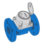
Typical Use Cases for Multi‑Jet?
Multi‑jet suits wider flow ranges and sites with more turbulence risk. It supports reliable readings when the layout is busy.
I use multi‑jet in mixed‑use buildings, hotels and areas with variable flows. I still add straight pipe or a straightener. I bleed air and control vibration. I confirm outlet pressure and real demand against Q ranges from the testing method.
Where multi‑jet holds accuracy across patterns
Multi‑jet meters help when low flow makes up a large share of daily use. Hotels and hospitals often have night flow from leaks or small fixtures. The multi‑jet impeller stays stable because jets distribute force evenly. This does not remove the need for straight pipes. ISO 4064 calls for straight lengths or a straightener whenever disturbances exist, so installed indications stay within MPE. I check outlet pressure and verify testing flow ranges to match site demand against the Q1, Q2 and Q3 bands used in lab error checks. I also bleed air and avoid shock during install, which follows the test bench guidance. When upstream work ends, I flush lines to remove debris because solids collect inside meters after pipe work, and that can raise complaints if not cleaned. With these habits, multi‑jet meters deliver steady data that matches billing needs.
| Site Type | Why Multi‑Jet | What I Verify |
|---|---|---|
| Hotels | Low flow sensitivity | Night flow pattern |
| Mixed‑use | Turbulence tolerance | Straight lengths |
| Hospitals | Stable low flows | Q1 accuracy |
| Busy manifolds | Distributed jets | Straightener option |
Common Installation Mistakes We See in the Field?
I see the same mistakes on repeat jobs. Each mistake has a clear fix if we respect the standard and basic site checks.
The first mistake is no straight pipe where bends or valves exist. ISO 4064 says the installed meter must have straight lengths or a straightener so it meets MPE. The second mistake is air not bled out, which test procedures warn against to avoid false counts and shock effects. The third mistake is ignoring outlet pressure and influence limits used in lab error checks.
The repeat offenders and how we fix them
I keep a simple list. If the meter sits right after a bend or valve, I add straight pipe. The standard is clear that upstream and downstream disturbances require straight lengths or a straightener so the installed indications meet MPE. If the reading looks high at start‑up, I bleed air. The ISO procedure reminds us to purge air and avoid vibration and shock, which can distort counts at test start and end. If the site shows erratic readings, I check outlet pressure and confirm temperature and other influences are within operating limits, like in the lab method that sets minimum outlet pressure and flow error ranges. After upstream works, I flush lines because solids collect in the meter. I have opened meters and found sand and scale inside after pipe work. These fixes are simple. They work.
| Mistake | Symptom | Fix |
|---|---|---|
| No straight pipe | Bias, scatter | Add straight length or straightener |
| Air left inside | Creep, false counts | Bleed air, refill slowly |
| Low outlet pressure | Cavitation, noise | Stabilize pressure ≥ 0.03 MPa |
| Debris after works | Blockage | Flush, clean strainer |
How to Choose the Right Type with Confidence?
I choose by site reality first and by catalog second. I follow ISO rules on installation, testing ranges, and influence controls.
I start with demand profiles and acceptable headloss. I check water quality and pipe layout. I match single‑jet or multi‑jet to these facts. I plan for straight pipe, air bleeding, and outlet pressure checks, because these are baked into ISO 4064 test and installation rules. I follow maker installation notes for special principles if used. I confirm the lab test program and references so the team understands Q‑range accuracy (Q1, 第2四半期, Q3) and document needs.
A simple, repeatable selection path
I use a short path for every project. I gather real flow data from a pilot or past bills. I set acceptable headloss. I review water quality and upstream works. If the site is clean and simple, single‑jet can be the most efficient. If low flow is common or turbulence risk is high, I lean to multi‑jet. I then lock installation basics. ISO 4064 calls for straight pipe or a straightener when disturbances exist, so installed readings meet MPE. The lab method requires bleeding air and avoiding shock and vibration, so I build those steps into my field checklist. I verify outlet pressure and hold influence factors within meter ratings, which mirrors test flow error checks at Q1, Q2 and Q3. If the project uses special sensors, I follow the maker’s installation rules and any flow conditioning needs. I also align the test program and documents against the standard’s references for verification, so everyone knows the accuracy basis.
| ステップ | Why It Matters | Tool |
|---|---|---|
| Demand profile | Match Q ranges | Pilot logging |
| Headloss target | Comfort and hydraulics | Design limits |
| Water quality | Debris risk | Flush plan |
| Pipe layout | Flow stability | Straight pipe |
| Air and pressure | Start‑up stability | Bleed and gauge |
| Standards mapping | MPE assurance | ISO 4064 checklist |
結論
Most “inaccurate” complaints come from installation conditions that ignore ISO 4064, not from the meter type. Choose by site reality and follow the simple rules.